8. Cnc25D API Working with FreeCAD
8.1. import FreeCAD
cnc25d_api. importing_freecad()FreeCAD comes with Python modules. But these FreeCAD modules are not installed in one of the standard directories. You will find the Python FreeCAD modules in a directory such as /usr/lib/freecad/lib. To use FreeCAD from a Python script, you need either to set the PYTHONPATH system environment variable or to extend the sys.path Python variable.
Because you need to import FreeCAD at each beginning of scripts, this task as been implemented in the module cnc25d_api.py that is installed in a standard location. So, after installing Cnc25D, to use the FreeCAD modules, you only need to add those lines at the beginning of your Python script:
from cnc25d import cnc25d_api
cnc25d_api.importing_freecad()
The function importing_freecad() looks for the FreeCAD modules using a location list. If the function importing_freecad() doesn’t manage to find FreeCAD on your system, you may need to edit the module importing_freecad.py and add the path to the FreeCAD modules to the FREECADPATH list.
8.2. place_plank()
cnc25d_api. place_plank( FreeCAD.Part.Object, x-size, y-size, z-size, flip, orientation, x-position, y-position, z-posistion )FreeCAD provides the usual rotate and translate methods to place an object in a construction-assembly. Even if those methods are mathematically straight forward, they might require many tries and errors to find out the correct rotation to apply to an object to place it correctly in an assembly. The place_plank() function provides an alternative to the rotate method when you want to place a object in a cuboid assembly.
To help positioning object we have the following conventions:
- The largest size of an object defines the main axis of the object.
- The second largest size of an object defines the second axis of the object.
- During the object construction, we choose the X axis as main axis and the Y axis as second axis.
A cuboid assembly is a construction where most of the objects have their main axis parallel to the X, Y or Z-axis. To place an object, construed with the above conventions, in a cuboid assembly, you can define the rotation of the object with two natural parameters:
- the orientation of the main and second axis. There are just six possibilities: ‘xy’, ‘xz’, ‘yx’, ‘yz’, ‘zx’ and ‘zy’. For example, ‘yx’ means that the main axis of the object is parallel to the Y-axis of the reference frame and the second axis of the object is parallel to the X-axis.
- the flip of the object. After defining the orientation of the main axis and second axis, there are still four possibilities called flip: ‘identity’, ‘x-flip’, ‘y-flip’ and ‘z-flip’.
The place_plank() function uses this approach to place a object in an cuboid assembly. To realize flip and orientation, the place_plank() function needs to know the sizes along X, Y and Z of the object. Those sizes are virtual and you can play with them for your convenience.
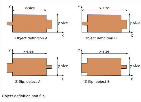
A physical object can be defined in several ways respecting our main and second axis conventions. The choice of the definition influences the behavior of the flip. Knowing that, choose the most convenient definitions for your design.
Look at the Plank Positioning Details chapter to get more explaination on rotation, orientation and flip transformations.
8.3. Drawing export
FreeCAD provides very efficient methods for 3D export such as .exportBrep(), .exportStep() or .exportStl(). It also provides full customizable 2D export methods such as .slice() and projectToDXF(). Cnc25D provides simple functions that covers the most standard usage of the 2D export.
8.3.1. Cut export as DXF
export_2d. export_to_dxf( FreeCAD.Part.Object, FreeCAD.Base.Vector, depth, path )The export_to_dxf() function performs two successive operations:
- It cuts a slice of the FreeCAD.Part.Object according to the direction FreeCAD.Base.Vector and the depth.
- It writes the DXF file path containing the projection of the slice.
If you are designing a 2.5D part, this function is useful to get the DXF file that will be used by the CNC workflow.
Usage example:
export_2d.export_to_dxf(my_part_solid, Base.Vector(0,0,1), 1.0, "my_part.dxf")
8.3.2. Cut export as SVG
export_2d. export_to_svg( FreeCAD.Part.Object, FreeCAD.Base.Vector, depth, path )The export_to_svg() function performs the same operations as export_to_dxf() except it write a SVG file.
Usage example:
export_2d.export_to_svg(my_part_solid, Base.Vector(0,0,1), 1.0, "my_part.svg")
Warning: The function export_to_svg() only works when it is used in a script run from the FreeCAD GUI. This is because of a current limitation of the FreeCAD library function Drawing.projectToSVG().
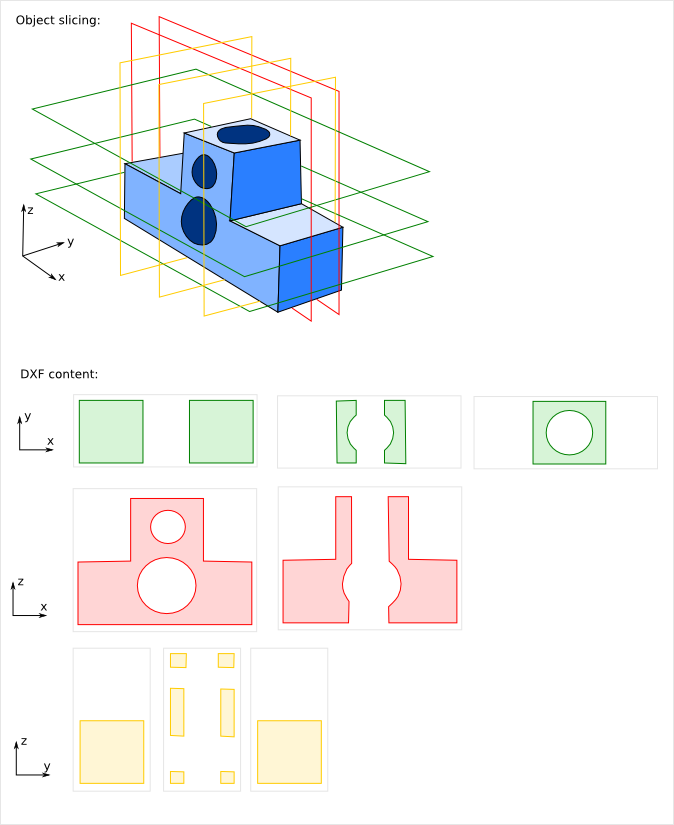
8.3.3. XYZ scanning
export_2d. export_xyz_to_dxf( FreeCAD.Part.Object, x-size, y-size, z-size, x-list, y-list, z-list, path )The export_xyz_to_dxf() function cuts in many slices the FreeCAD.Part.Object according to the three directions of the reference frame axis X, Y and Z. The depth of the slices are provided by the three argument lists x-list, y-list and z-list. All the slices are placed in the plan XY and are written in the DXF file path.
The result looks like a medical scan. This is a more comfortable and readable document than the CAD tradition 3 views projections. This helps to show up weaknesses of designs if you choose good slices.
Usage example:
xy_slice_list = [ 0.1+20*i for i in range(12) ]
xz_slice_list = [ 0.1+20*i for i in range(9) ]
yz_slice_list = [ 0.1+20*i for i in range(9) ]
export_2d.export_xyz_to_dxf(my_assembly, 180.0, 180.0, 240.0, xy_slice_list, xz_slice_list, yz_slice_list, "my_assembly.dxf")