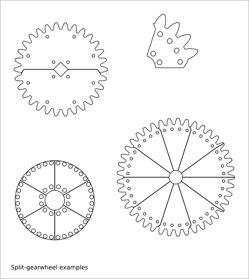
24. Split-gearwheel Design
Ready-to-use parametric split-gearwheel design (i.e. spur that is split for its fabrication).
To get an overview of the possible split-gearwheel designs that can be generated by split_gearwheel(), run:
> python split_gearwheel.py --run_self_test
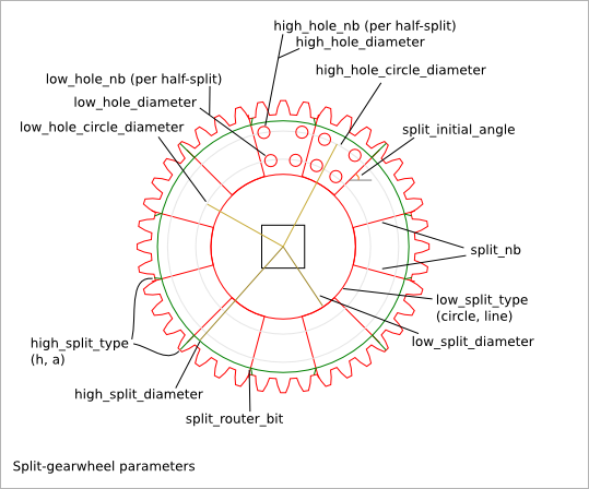
24.1. Split-gearwheel Parameter List
The parameter relative to the gear-profile are directly inherit from the Gear Profile Function.
24.2. Split-gearwheel Parameter Dependency
24.2.1. router_bit_radius
Three router_bit radius are defined: gear_router_bit_radius, split_router_bit_radius, and cnc_router_bit_radius. Each set the router_bit radius for different areas except cnc_router_bit_radius that set the mimnimum value for the two other router_bit radius. If an other router_bit radius is smaller than cnc_router_bit_radius, it is set to cnc_router_bit_radius. So, we have the relations:
cnc_router_bit_radius < gear_router_bit_radius
cnc_router_bit_radius < split_router_bit_radius
24.2.2. split_nb
split_nb defines in how many parts the gearwheel must be split. The split_gearwheel() function generates two sets (A and B) of split_nb parts. So you get at the end 2*split_nb parts. The set A (respectively B) makes a complete gearwheel. The set-A-gearwheel and the set-B-gearwheel can be stick together to ensure a better stability. The low-holes and high-holes ensure a good alignment between the set-A parts and set-B parts. The parameters low_hole_nb and high_hole_nb define the number of holes per half-split-portion i.e. the common portion between a set-A parts and a set-B part.
24.2.3. low_split_diameter and high_split_diameter
The constraints define 5 circles: low_split_diameter, low_hole_circle_diameter, high_hole_circle_diameter, high_split_diameter and minimal_gear_profile_radius (inferred from the gear-profile). If gear_tooth_nb = 0 then high_split_diameter = minimal_gear_profile_radius. These five circles are strictly included in each others:
low_split_diameter + low_hole_radius < low_hole_circle_diameter
low_hole_circle_diameter + low_hole_radius + high_hole_radius < high_hole_circle_diameter
high_hole_circle_diameter + high_hole_radius < high_split_diameter
high_split_diameter < minimal_gear_profile_radius
24.2.4. low_split_type
low_split_type defines the outline at the low-split-circle:
circle : the outline is an arc of circle
line   : the outline is composed of two lines
24.2.5. high_split_type
high_split_type defines how to join the split radius with the gear-profile. Indeed the number of gear-teeth and the number of split-portion are independant. In most of the case, the gear-hollow doesn’t fit exactly the split radius. The split radius stops at the high-split circle. Then, the outline goes straight to the gear-profile. The angle at the high-split circle is smooth with split_router_bit_radius. The possible values for high_split_type are:
'h': the outline goes to the closest gear-hollow middle
'a': the outline goes to the addendum middle if it best fits, otherwise it goes to the closest gear-hollow middle
24.2.6. gear_tooth_nb
gear_tooth_nb sets the number of teeth of the gear_profile. If gear_tooth_nb is set to zero, the gear_profile is replaced by a simple circle of diameter gear_primitive_radius.
24.2.7. Alignment angles
gear_initial_angle sets the angle between the X-axis and the middle of the addendum of the first tooth. split_initial_angle sets the angle between the X-axis and the first split radius. Use gear_initial_angle or split_initial_angle or both to ajust the offset angle between the gear-profile anf the split-portion.